
Backstory
I’m currently in the process of building my own CNC router. This router will be controlled by an arduino, and will help me in future DIY projects. However, there’s been some issues with the arduino randomly freezing, and end switches (wired as NO) randomly triggering. As it mostly seemed to happen when turning on the spindle, I started looking into electromagnetic interference. The biggest problem? I don’t have a clue what generates interference, how much interference is too much, and how much is already present near every day objects. Please note that I am not an electrical engineer, and as such, there is a lot of room to improve on this detector.
Materials
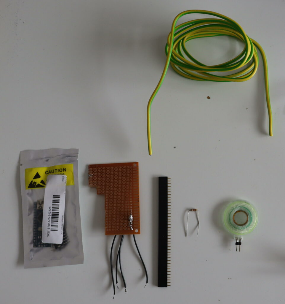
For this build we’ll need the following materials:
- 1m of solid-core wire
- A speaker
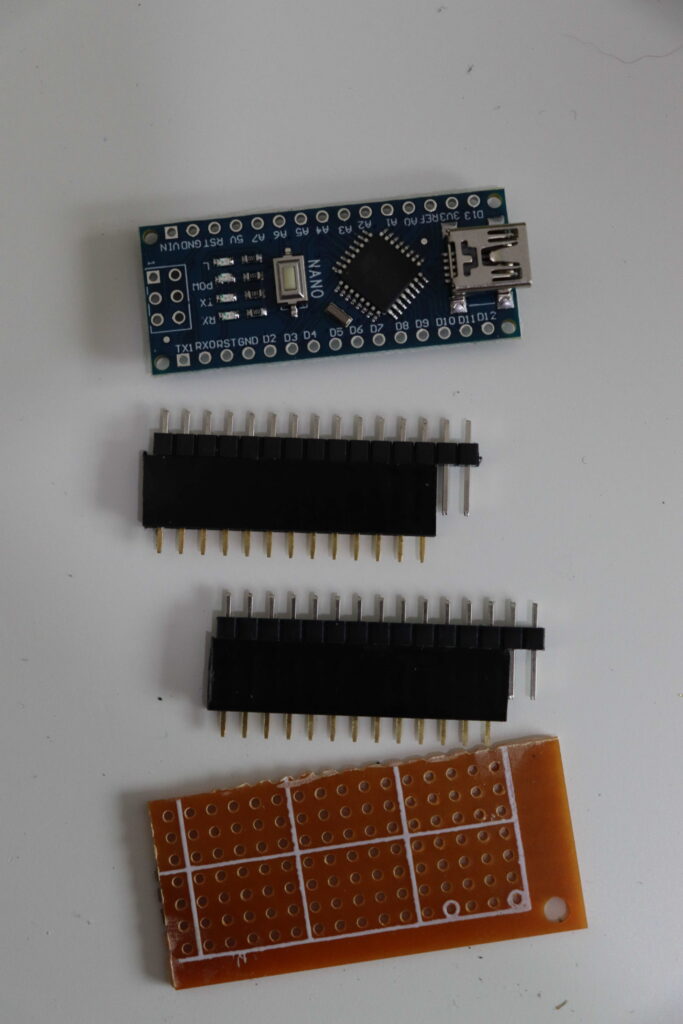
- An Arduino (Nano, in my case. Any should do though.)
- Some prototyping board. (Mine already had some wires attached, please ignore that.)
- A row of female headers.
- A resistor. I used 1K, but I’ve read that 1M may work better.
The build
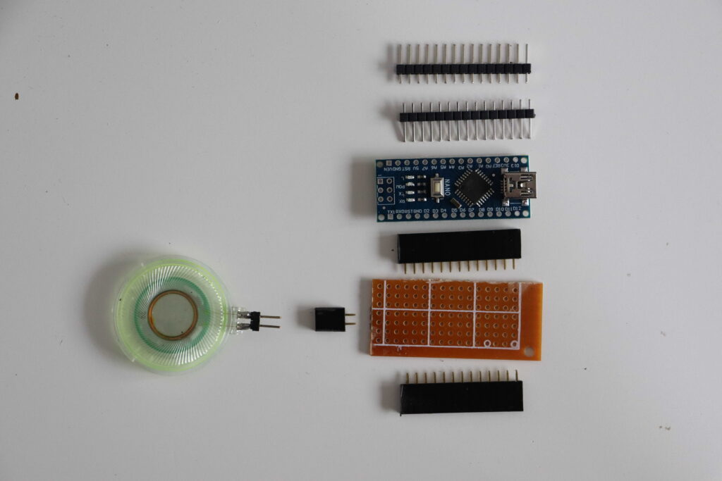
The first step is to cut a piece of the prototyping board, roughly the size of the arduino. Also cut off three pieces of female headers. One for either side of the arduino, and one for the speaker. The speaker one needs to be two holes wide, the ones for the arduino need to be at least 5 pins wide. We won’t be using the rest of the pins, but it doesn’t hurt to have more for structural stability.
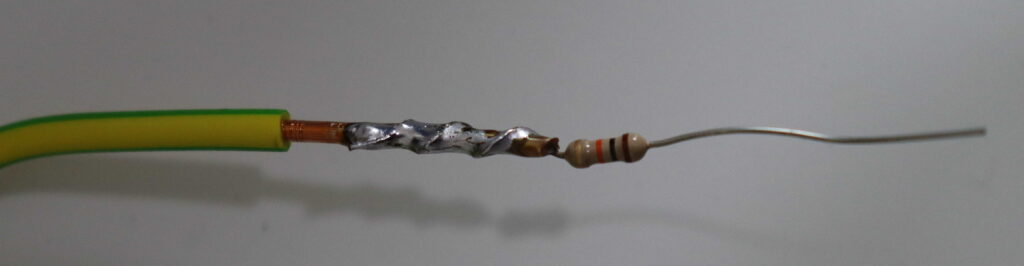
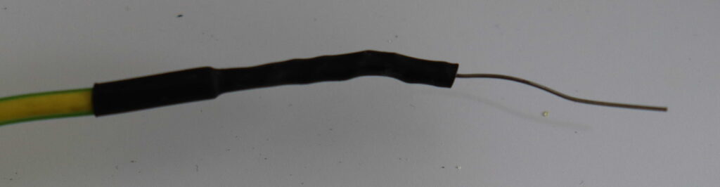
Next, strip the ends of the solid core wire. Take off around 1cm on the one end, and roughly the length of a leg of the resistor on the other. Wrap one leg of the resistor around the wire, and solder them together. Cover the end of the wire and the resistor with some shrink wrap.
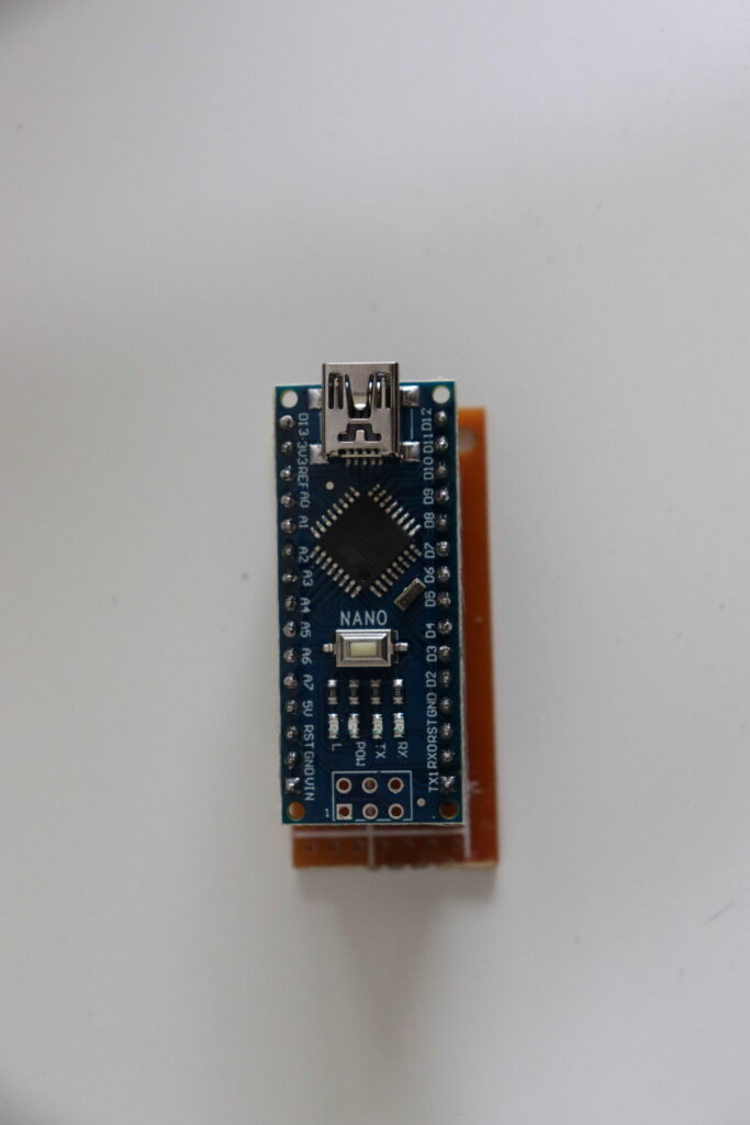
For soldering the Arduino and the PCB, I’ve found that it helps to first “assemble” the headers. Putting all components in place before soldering helps to keep everything nice and lined up. If everything is still skewed, consider placing two prototyping boards underneath everything while soldering the Arduino, to lift up the pins and keep everything straight. First solder the corners on the Arduino, and then solder all other pins. After soldering the Arduino, flip it over, and solder the breadboard. Don’t forget to clean it after cutting. I did forget, and the soldering looks messy as can be. (But it works, so I don’t care for now.)
Also solder the header for the speaker in place, behind the Arduino. At this point it should look something like the image above.
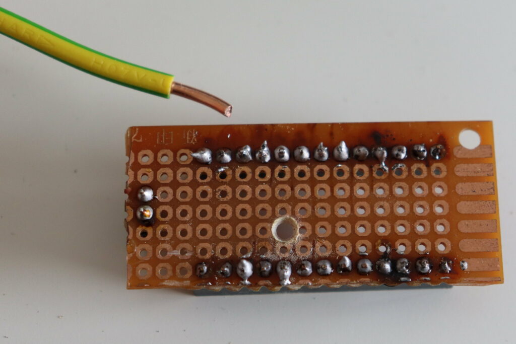
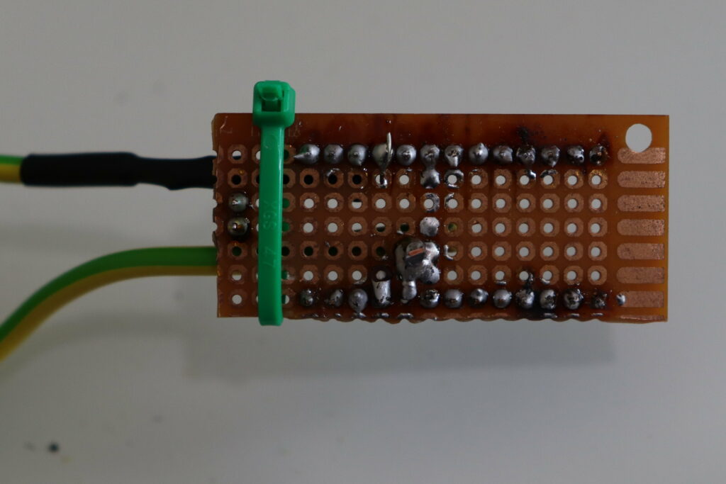
Drill a hole in the prototyping board for the solid core wire to fit through, close to the A7 pin. (Take off the Arduino and speaker before doing so, of course.) Solder the solid core wire in place, and create a bridge to the A7 pin. Wire the resistor to any of the ground pins. I used a ground pin across from the A7 pin, because it’s easier to route the wires next to the 2-pin header for the speaker. It can help here to use a zip tie to keep the wires in place, for some added structural integrity.
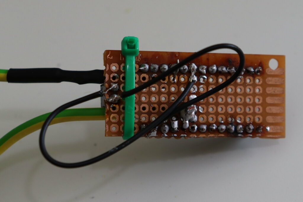
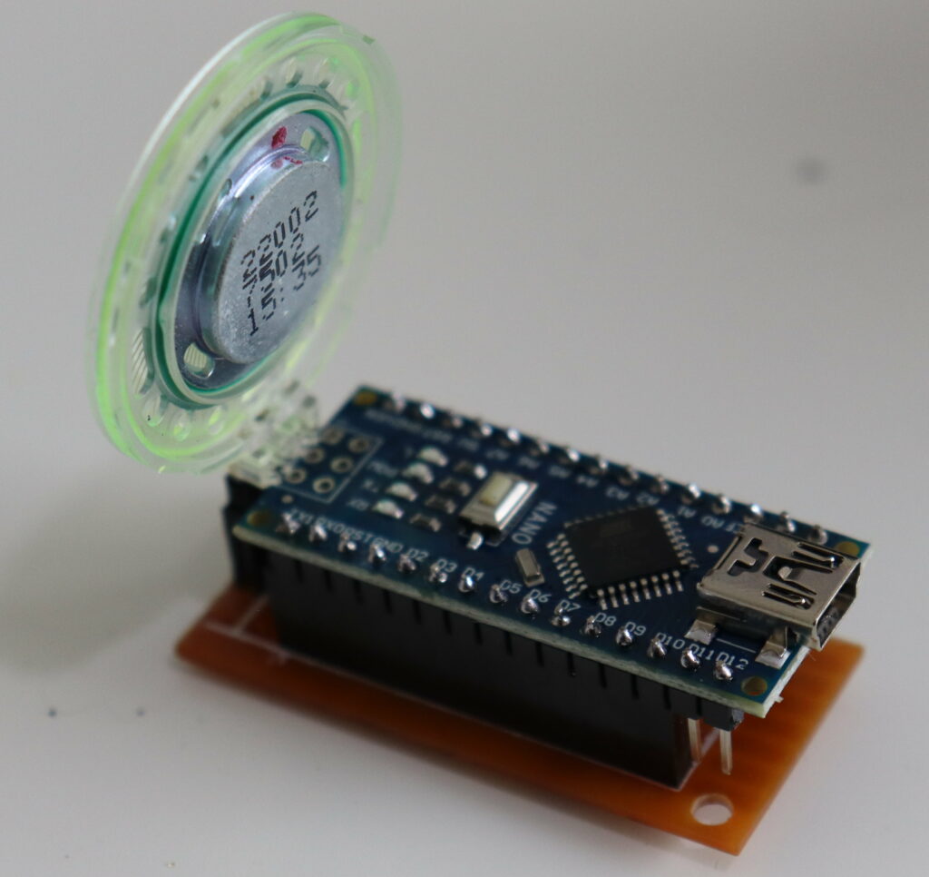
Create a bridge from digital pin 3 to one of the speaker pins, and connect the other speaker pin to a ground pin.
Now our detector is ready for a test run! Hook it up to your PC, and upload the Arduino project to it. It may give a constant low hum. Move the “antenna” to something that should give off an electromagnetic field (e.g. a laptop power adapter), and listen for the tone to change. This indicates that it’s working!
constexpr const int delayTime = 250;
constexpr const int pinIn = A7;
constexpr const int pinSpeaker = 3;
int value = 0;

void setup()
{
  Serial.begin(9600);
}

void loop()
{
 value = analogRead(pinIn);
 if (value == 0){
  return;
 }
 Serial.println(value);
 value = map(value, 1, 100, 1, 2048);
 tone(pinSpeaker, value, delayTime);
}
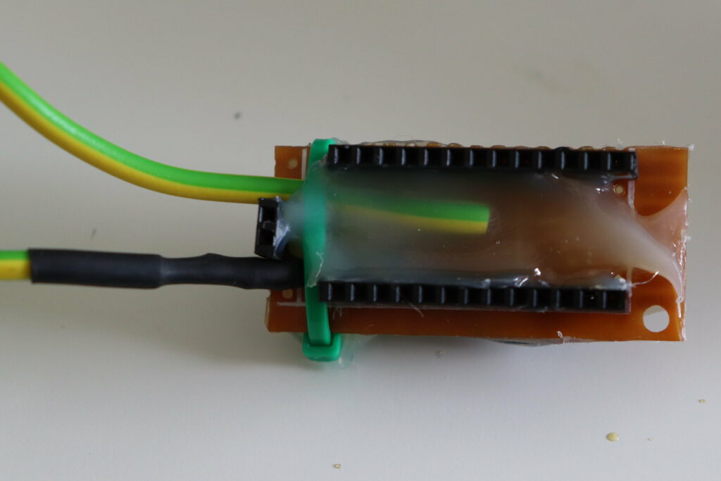
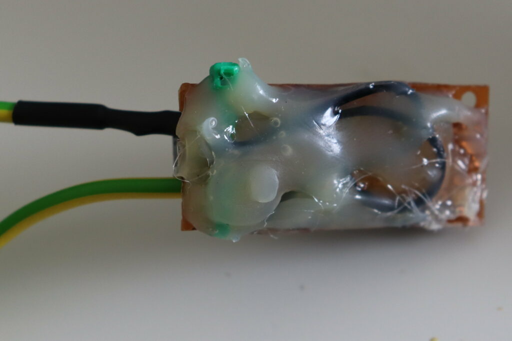
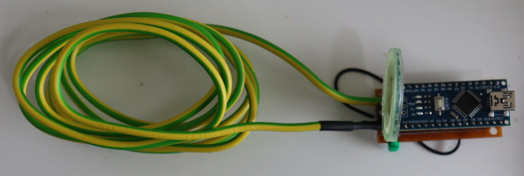
Now I’ve seen a couple too many wires break loose from their soldering connections, so I tend to cover my projects in a fair amount of hot glue. This reduces the chance of any of the wires ever breaking loose. (And, it hides any ugly soldering work with more ugly hot-glue work.) After hot-gluing, reassemble it. Use the USB port to connect the Arduino to a power bank, and you’ll have a fully functional portable EMI detector!
Now as I said, I am not an electrical engineer, and I did not experiment a lot with this. You may find that unrolling the antenna, or rolling it into a tighter coil, would give better performance. Different values for the resistor or changes in the delay between samples in the code can also affect the performance. If you build this too and find that doing something differently works better, please do let me know in the comments down below!
How does it actually work?
Okay, so here comes the disclaimer again: I don’t actually know. But my assumption is as follows. The resistor on the wire is there to make sure that the wire/antenna slowly discharges. The antenna acts as a coil, which is slowly charged by an alternating magnetic field. This field is what we’re measuring with the analog input. A higher alternating electromagnetic field means more interference, and means a higher value on the analog input. The code then translates this value into a beep of a specific tone. When more power is received by the antenna, the beep frequency goes up.
How well does it work?
For the purpose of which I built it, it actually works very well. But then again, my goal was set very low. I simply wanted to get a bit of a feeling for what generates electromagnetic fields and what doesn’t, and that worked. I did notice two problems though. Firstly, touching the analog pin, causes a beep. This is probably because the human body seems to generate a low electrical current. Try holding a 3.5mm jack that’s plugged into some speakers, they’ll start humming. The same happens here. Secondly, either electromagnetic fields vary a lot, or the device is not very accurate. Sometimes after moving away from an object the detector kept giving off a beep for a while, while other times it didn’t. Sometimes it would even start beeping “randomly”. However, moving around devices a couple times would give me quite a good indication of what were random beeps and what actually consistently caused a beep to go off. I think this could be fixed by rolling the antenna into a more tight coil, but I am not sure. For the noise generated when touching the analog pin I could make a nice case around the device, but I don’t think I will for now. It’s useful enough as is for me to find sources of interference on my CNC router, and after that I don’t expect to be using it very often. So all in all, this project was quite a succes!
This project was posted on hackaday on the 21st of may, 2021.